Oct 12, 2022
What is a shielded wire?
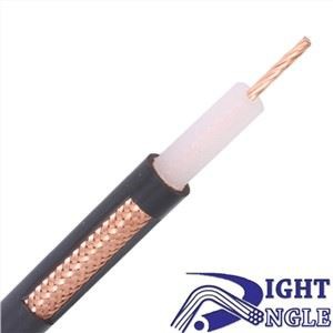
Definition: A conductor wrapped with a conductor outside the conductor is called a shielded wire, and the wrapped conductor is called a shielding layer, which is generally a braided copper mesh or copper moor (aluminum).
Function: prevent interference signals from entering the inner layer, conductor interference and reduce the loss of transmission signals.
Structure: (ordinary) insulating layer + shielding layer + wire; (advanced) insulating layer + shielding layer + signal wire + shielding layer grounding wire
Note: When selecting shielded wires, the insulating layer of the shielding layer grounding wire shielding layer grounding wire has a conductive function and can be connected to the shielding layer (with a certain resistance).
The principle of shielded cable:
The shielded wiring system originated from Europe. It is a metal shielding layer added to the outside of the ordinary unshielded wiring system, and the reflection, absorption and skin effect of the metal shielding layer are used to prevent electromagnetic interference and electromagnetic radiation. The function of the shielding system comprehensively utilizes The balance principle of twisted pair and the shielding effect of the shielding layer, so it has very good electromagnetic compatibility (EMC) characteristics.
Electromagnetic compatibility (EMC) means that electronic equipment or network systems have a certain ability to resist electromagnetic interference, and at the same time cannot generate excessive electromagnetic radiation. That is to say, it is required that the device or network system can work normally in a relatively harsh electromagnetic environment, and at the same time cannot radiate excessive electromagnetic waves to interfere with the normal operation of other surrounding devices and networks.
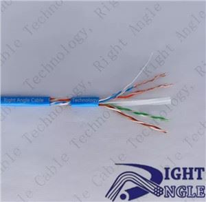
The balanced characteristics of U/UTP (unshielded) cables are not only determined by the quality of the components themselves (eg twisted pairs), but are also affected by the surrounding environment. Because metal around U/UTP (unshielded), hidden "ground", pulling during construction, bending, etc. will destroy its balance characteristics, thereby reducing EMC performance.
So, there is only one solution to get lasting balanced characteristics: ground all cores with an extra layer of aluminum foil. Aluminum foil adds protection to the fragile twisted-pair cores, while artificially creating a balanced environment for U/UTP (unshielded) cables. Thus forming what we now call a shielded cable.
The shielding principle of the shielded cable is different from the balanced cancellation principle of the twisted pair. The shielded cable is to add one or two layers of aluminum foil on the outside of the four pairs of twisted pairs, and use the metal to reflect, absorb and skin effect principles of electromagnetic waves (the so-called trend). The skin effect means that the distribution of the current in the conductor cross-section tends to be distributed on the surface of the conductor with the increase of the frequency. Electromagnetic interference enters the cable, but also prevents the internal signal from radiating out, interfering with the work of other equipment.
Experiments show that electromagnetic waves with frequencies exceeding 5MHz can only pass through 38μm thick aluminum foil. If the thickness of the shielding layer exceeds 38 μm, the frequency of electromagnetic interference that can enter the cable through the shielding layer is mainly below 5MHz. For low-frequency interference below 5MHz, the balance principle of twisted pair can be applied to effectively cancel.
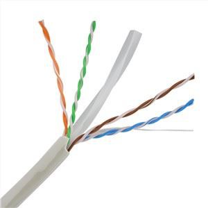
According to the earliest definition of wiring, it is divided into two types: unshielded cable-UTP and shielded cable-STP. Later, with the development of technology and different craftsmanship, many different types of shielding were derived. F/UTP Foil Screened Cable Single-layer aluminum foil shielding structure 2. Foil and Braid Screened Cable Double-layer shielding structure of aluminum foil and copper braid a) SF/UTP aluminum foil and copper braid wrapped on the outer layer of four pairs of wires at the same time b) S/FTP (PIMF) wire pair single pair of aluminum foil shielding plus The copper braided mesh PIMF =Pair in Metal Foil wrapped on the outer layer of the four pairs of wires.
The shielded cable's resistance to external interference is mainly reflected in: the integrity of signal transmission can be guaranteed by the shielding system. The shielded wiring system can prevent the transmitted data from being affected by external electromagnetic interference and radio frequency interference. Electromagnetic Interference (EMI) is mainly low frequency interference. Motors, fluorescent lamps and power lines are common sources of EMI. Radio frequency interference (RFI) is high frequency interference, mainly radio frequency interference, including radio, television broadcast, radar and other wireless communications.
For resistance to electromagnetic interference, braided shielding is the most effective choice, that is, metal mesh shielding, because of its low critical resistance. For radio frequency interference, metal foil shielding is the most effective, because the gap created by the metal mesh shield allows high-frequency signals to enter and exit freely. For the mixed interference field of high and low frequency, the combined shielding method of metal foil layer and metal mesh should be used, that is, the double-layer shielded cable in the form of S/FTP, which can make the metal mesh shielding suitable for interference in the low frequency range, and the metal foil shielding Suitable for interference in the high frequency range.
The single-layer thickness of the aluminum foil shielding layer in the IBM ACS shielded cable reaches 50-62 μm, which has a more complete shielding effect. At the same time, because only a single layer of shielding is used, it will be simpler for construction, easy to install, and not easy to cause artificial damage during the construction process, and the thickness of the aluminum silk can withstand greater destructive force. This can provide users with higher quality transmission performance.
Shielded wire connection:
One end of the shielded wire is grounded, and the other end is left floating.
When the transmission distance of the signal line is relatively long, the potential of the two grounding points may be different due to the different grounding resistances at both ends or the current in the PEN line. Therefore, in this case, one point is generally grounded, and the other end is suspended, which can avoid the formation of such interference.
Ground shielding at both ends is better, but signal distortion will increase.
Please note: The two layers of shielding should be mutually insulated and isolated shields! If not insulated from each other, it should still be regarded as a single shield!
The grounding of both ends of the outermost shield is due to the induced current due to the introduced potential difference, thus generating a magnetic flux that reduces the strength of the source magnetic field, thereby basically canceling out the voltage induced when there is no outer shield;
And one end of the innermost shield is grounded, because there is no potential difference, it is only used for general anti-static induction. The following specifications are the best evidence!
"GB 50217-1994 Code for Design of Electric Power Engineering Cables" - 3.6.8 The grounding method of the metal shield of the control cable shall meet the following requirements:
(1) The shielding layer of the analog signal loop control cable of the computer monitoring system shall not be grounded at two or more points, and a centralized one-point grounding should be used.
(2) For the shielding layer of the control cable, except for the case of item (1), which requires one point of grounding, when the interference of electromagnetic induction is large, two points of grounding should be used; if the interference of electrostatic induction is large, one point of grounding can be used.
For double shielding or composite overall shielding, one point should be used for the inner and outer shielding, and two points should be grounded.
(3) The choice of two-point grounding should also consider that the shielding layer will not be melted under the action of transient current.
"GB50057-2000 Design Code for Lightning Protection of Buildings" - Article 6.3.1 stipulates: ... When shielded cables are used, the shielding layer should be equipotentially connected at least at both ends, and when the system requires only one end of the equipotential bonding , two layers of shielding should be used, and the outer shielding should be handled according to the aforementioned requirements.
The principle is: 1. One end of the single-layer shield is grounded, and no potential difference is formed. It is generally used for anti-static induction. 2. Double-layer shielding, both ends of the outermost shield are grounded, and one end of the inner shield is grounded with equipotential grounding. At this point, the outer shield induces a current due to the potential difference, thus generating a magnetic flux that reduces the strength of the source magnetic field, thereby substantially canceling the voltage induced without the outer shield.
If it is to prevent electrostatic interference, it must be grounded at a single point, whether it is a one-layer or two-layer shielding. Because single-point grounding has the fastest rate of electrostatic discharge.
However, there are two exceptions:
1. There is strong current interference outside, and single-point grounding cannot meet the fastest discharge of static electricity.
If the cross-sectional area of the grounding wire is large and can ensure the fastest discharge of static electricity, it should also be grounded at a single point. Of course, if that's the case, there's no need to opt for two layers of shielding.
Otherwise, two layers of shielding are required. The outer shielding is mainly to reduce the interference intensity, not to eliminate the interference. At this time, it must be grounded at multiple points. Although it cannot be put out, it must be weakened as soon as possible. To weaken it, multi-point grounding is the best choice.
For example, the cable tray in the enterprise is actually the outer shielding layer, which must be grounded at multiple points. The first line of defense is to reduce the intensity of the interference source.
The inner shielding layer (in fact, you will not buy double-layer cables, generally the outer layer is the cable tray, and the inner layer is the shielding layer of the shielded cable) must be grounded at a single point, because the external strength has been reduced, discharge as soon as possible to eliminate interference That's the inner purpose.
2. Safety requirements such as external electric shock and lightning protection.
In this case, two layers of protection are required. The outer layer is not used to eliminate interference, but for safety reasons. To ensure the safety of people and equipment, multiple points must be grounded. The inner layer is to prevent interference, so it must be grounded at a single point.
The role of shielded wire:
The function of the shielded wire is to isolate the electromagnetic field noise source from the sensitive equipment and cut off the propagation path of the noise source. Shielding is divided into active shielding and passive shielding. The purpose of active shielding is to prevent the noise source from radiating outward, which is the shielding of the noise source; the purpose of passive shielding is to prevent the sensitive equipment from being interfered by the noise source, which is the shielding of the sensitive equipment.
The shielding layer of the shielded cable is mainly made of non-magnetic materials such as copper and aluminum, and the thickness is very thin, which is much smaller than the skin depth of the metal material at the frequency of use. The effect of the shielding layer is not mainly due to the reflection of the electric field and magnetic field by the metal body itself. , absorption, but due to the grounding of the shielding layer. Different grounding forms will directly affect the shielding effect. The grounding methods of the electric field and magnetic field shielding layers are different. Ungrounded, single-ended or double-ended
Summarize:
Single-ended ground:
1) Single-ended grounding of shielded cables is helpful to avoid interference from low-frequency electric fields. In other words, it can avoid frequency interference whose wavelength λ is much larger than the cable length L. L<λ /20
2) Single-ended grounding of the cable shield can avoid low-frequency current noise on the shield. This current internally causes common-mode interference voltages and can potentially interfere with analog devices.
3) The single-ended grounding of the shielding layer is desirable for those circuits (analog circuits) that are sensitive to low-frequency interference.
4) Fluctuations and permanent deviations of continuous measurement values indicate low frequency disturbances. Double-ended grounding: a. Make sure the connection to the control cabinet or plug (round contact) goes through a large conductive area (low inductance). Choose metals over metals rather than non-metals over non-metals. b. Since some analog modules use pulse technology (for example: processor and A/D converter are integrated in the same module), it is recommended to shield the analog signals from each other to ensure correct equipotential bonding, only in this case Double-ended grounding. c. Usually, the transmission impedance of the metal foil shielding layer is much larger than that of the copper braided wire, and its effect is 5-10 times different, so it cannot be used as a digital signal cable. d. Occasional malfunctions indicate high frequency interference. This is something that cannot be eliminated by wire equipotential bonding.
5) It is advantageous to ground the shield at multiple points other than the end of the cable.
6) Do not connect the shielding layer to the pins to avoid the "pig tail" phenomenon.
7) Always pay attention to the parallel impedance of the shielding layer should be less than 1/10 of its own impedance. Cable trays, mechanical frames, other shields, or other parallel cables can make the system equipotential.
8) If the shielding layer of the cable heats up when the shielding layer is grounded at both ends, or the shielding layer catches fire when it touches the shell of the electric control cabinet or the shielded bus, it means that the equipotential bonding is not reliable.